Ford Focus Service Manual: Manual Transaxle/Transmission - MTX75
The MTX-75 manual transaxle features the following:
- Two-part aluminum housing
- The input shaft has 2 tapered roller bearings. Input shaft end play is controlled by a selective shim located under the bearing cup
- The output shaft has 2 tapered roller bearings. Output shaft end play is controlled by a selective shim located under the bearing cup
- The differential has 2 tapered roller bearings. Differential end play is controlled by a selective shim located under the bearing cup
- All gears are bevel cut
- All gears, including reverse, turn on needle bearings
- Synchronized in all gears
- First and 2nd gear are dual synchronized
- Single piece brass shift forks
The input shaft, output shaft and the differential assembly are assembled under preload. If the transmission is disassembled, a preload measurement must be taken.
The transmission's function is to move the vehicle from a rest position to motion. This is done by transferring the engine torque, through the transaxle, to the vehicle's front wheels. The transmission uses gears to adapt the torque to the demands of load and road conditions. It matches engine power to vehicle needs.
This power is delivered from the engine's flywheel, to the transaxle. The power is transmitted through a driver-operated clutch, which allows for engagement and disengagement of the engine to the transaxle.
Power Flow
General View of the Input and Output Shaft

| Item | Part Number | Description |
|---|---|---|
| 1 | 7017 | Input shaft |
| 2 | 7061 | Output shaft |
| 3 | 7141 | Reverse gear idler |
| 4 | 7112 | Fourth gear |
| 5 | 7124 | Third and 4th gear synchronizer |
| 6 | 7B340 | Third gear |
| 7 | — | Output drive pinion |
| 8 | 7100 | First gear |
| 9 | 7124 | First and 2nd gear synchronizer |
| 10 | 7102 | Second gear |
| 11 | 7K316 | Fifth gear |
| 12 | 7124 | Fifth and reverse gear synchronizer |
| 13 | 7141 | Reverse gear |
1st Gear
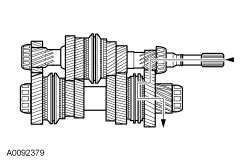
- The input shaft drives the output shaft.
- The 1st gear on the input shaft drives 1st gear on the output shaft.
- The 1st/2nd gear synchronizer is splined to the output shaft.
- When the 1-2 synchronizer sleeve is shifted forward, 1st gear is locked to the output shaft.
- The output shaft drives the differential ring gear.
- The power flows through the side and pinion gears to the halfshafts.
2nd Gear
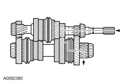
- The input shaft drives the output shaft.
- The 2nd gear on the input shaft drives 2nd gear on the output shaft.
- The 1st/2nd gear synchronizer is splined to the output shaft.
- When the 1-2 synchronizer sleeve is shifted rearward, 2nd gear is locked to the output shaft.
- The output shaft drives the differential ring gear.
- The power flows through the side and pinion gears to the halfshafts.
3rd Gear
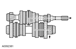
- The input shaft drives the output shaft.
- The 3rd gear on the input shaft drives 3rd gear on the output shaft.
- The 3rd/4th gear synchronizer is splined to the input shaft.
- When the 3-4 synchronizer sleeve is shifted forward, 3rd gear is locked to the input shaft.
- The output shaft drives the differential ring gear.
- The power flows through the side and pinion gears to the halfshafts.
4th Gear
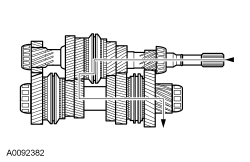
- The input shaft drives the output shaft.
- The 4th gear on the input shaft drives 4th gear on the output shaft.
- The 3rd/4th gear synchronizer is splined to the input shaft.
- When the 3-4 synchronizer sleeve is shifted rearward, 4th gear is locked to the input shaft.
- The output shaft drives the differential ring gear.
- The power flows through the side and pinion gears to the halfshafts.
5th Gear
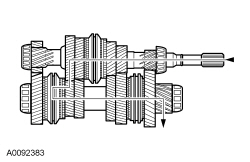
- The input shaft drives the output shaft.
- The 5th gear on the input shaft drives 5th gear on the output shaft.
- The 5th/reverse gear synchronizer is splined to the output shaft.
- When the 5th/reverse gear synchronizer sleeve is shifted forward, 5th gear is locked to the output shaft.
- The output shaft drives the differential ring gear.
- The power flows through the side and pinion gears to the halfshafts.
Reverse Gear
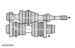
- The input shaft drives the reverse idler gear.
- The reverse gear on the input shaft drives reverse gear on the output shaft.
- The reverse gear synchronizer is splined to the output shaft.
- When the reverse gear synchronizer sleeve is shifted rearward, reverse gear is locked to the output shaft. The reverse idler gear drives reverse gear on the input shaft, in a reverse direction.
- The output shaft drives the differential ring gear.
- The power flows through the side and pinion gears to the halfshafts.
 Input Shaft
Special Tool(s)
Remover, Bearing/Gear
205-D064 (D84L-1123-A)
Material
Item
Specification
Motorcraft® Full Synthetic Manual Transmission Fluid ...
 Clutch System Bleeding
Special Tool(s)
Vacuum Pump Kit
416-D002 (D95L-7559-A)
Material
Item
Specification
High Performance DOT 3 Motor Vehicle Brake Fluid
PM-1- ...
More about Ford Focus:
Ford Focus Tire Pressure Monitoring System (TPMS) Sensor Training
Special Tool(s)
Activation Tool, Tire Pressure Monitor
204-363
Vehicle Communication Module (VCM) and Integrated Diagnostic System
(IDS)
software with appropriate hardware, or equivalent scan tool
NOTE: If the vehicle has been stationary ...
